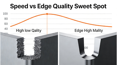
In laser cutting, speed sells—but quality seals the deal.
Every fabricator faces the same dilemma: How fast can I cut without sacrificing edge quality? Push too hard, and you get dross, roughness, or taper. Go too slow, and productivity plummets while costs rise.
Finding the sweet spot—the optimal balance between cutting speed and edge finish—is essential for competitive, high-quality manufacturing.
Let’s break down how to identify and maintain that perfect equilibrium.
Understanding the Trade-Off
Cutting speed directly affects:
Cycle time → impacts throughput
Heat input → influences HAZ (heat-affected zone), warping, and metallurgy
Edge characteristics → smoothness, squareness, burr formation
Meanwhile, edge quality determines:
Need for secondary operations (grinding, deburring)
Weldability and coating adhesion
Customer acceptance
There’s no universal “best” setting—only the best setting for your specific application.
Factors That Influence the Speed-Quality Curve
1. Material Type & Thickness
Thin mild steel (<3 mm): Can be cut very fast with excellent quality.
Thick stainless (>8 mm): Requires slower speeds to maintain clean edges.
Aluminum: Moderate speeds needed due to reflectivity and thermal conductivity.
2. Laser Source Power & Mode Quality
Higher power (6kW+) allows faster cutting with good edge control.
Single-mode lasers offer finer focus and cleaner cuts at high speeds on thin materials.
Multi-mode better for thick plates requiring wider kerfs and stable melt ejection.
3. Assist Gas Choice
Oxygen: Faster cuts on carbon steel (exothermic boost), but produces oxidized edges.
Nitrogen: Slower, more controlled fusion cutting; yields bright, burr-free edges ideal for welding or polishing.
Example: Cutting 3 mm stainless steel
With O₂: 3.5 m/min, blackened edge → needs post-processing
With N₂: 2.0 m/min, mirror-like edge → ready-to-assemble
4. Nozzle Design & Condition
A clean, properly sized nozzle ensures laminar gas flow. Even minor damage increases turbulence, reducing effective speed and degrading edge quality.
5. Focus Position & Beam Alignment
Misaligned beams or incorrect focal points reduce energy density, forcing operators to slow down to achieve acceptable cuts.
How to Find Your Sweet Spot
Follow this systematic approach:
🔍 Step 1: Define Acceptable Edge Quality**
Establish clear criteria:
Maximum allowable surface roughness (Ra ≤ 6 μm?)
No visible dross?
Taper < 0.1 mm?
Burr height < 0.08 mm?
Involve customers or downstream teams (welding, painting) in defining standards.
🔍 Step 2: Conduct Speed Ramp Tests**
Cut a series of test samples across a range of speeds (e.g., 1.0 → 3.0 m/min in 0.2 increments). Keep all other parameters constant.
Inspect each sample under magnification. Note:
Point where dross begins to form
When striation becomes excessive
Changes in top/bottom edge condition
Plot results on a graph: Speed vs. Defect Occurrence
🔍 Step 3: Measure Cycle Time Impact**
Calculate how much faster each increase saves. A 0.5 m/min gain on a 5-meter path saves ~6 seconds per part. Multiply by batch size.
Weigh time saved against rework cost if quality drops.
🔍 Step 4: Evaluate Total Cost Per Part**
Include:
Machine time ($/hour)
Labor
Gas consumption
Post-processing (deburring, cleaning)
Scrap rate
You may find that slightly slower cutting actually reduces total cost due to fewer touch-ups.
🔍 Step 5: Document and Standardize**
Once found, lock in the optimal parameter set. Save it in your process library with notes:
Material grade
Thickness
Gas type & pressure
Nozzle size
Focus position
Train operators to follow it consistently.
Smart Techniques to Extend the Sweet Zone
You don’t always have to choose between speed and quality—sometimes you can have both:
Corner slowdown: Reduce speed only at sharp corners; maintain high speed on straight sections.
Pierce delay optimization: Minimize dwell time without compromising hole quality.
Adaptive power control: Slightly boost power during difficult segments (holes, corners).
Hybrid cutting: Use oxygen for roughing, nitrogen for finishing (on select features).
Real-World Example
A manufacturer cutting 2 mm stainless enclosures increased speed from 22 to 28 m/min to meet demand. But inspection revealed increased bottom dross and required grinding on 40% of parts.
After testing, they settled at 25 m/min—still a 14% speed gain—with zero dross. Rework dropped to 2%, saving $18,000/year in labor alone.
Their sweet spot wasn’t maximum speed—it was maximum value.
Conclusion
The sweet spot isn’t fixed—it evolves with material lots, machine wear, and customer expectations. But by adopting a data-driven, test-based approach, you can continuously refine your processes.
Balance isn’t compromise. It’s precision engineering applied to production strategy.
Find your sweet spot—and stay there.
@taidinggroup
@taidinggroup